

First of all.
Be very careful, you can damage your tablet if you make an hardware variation or a version of BIOS not in conformity with your tablet model. I take absolutely no responsibility in both cases. If you haven't the right know-how to make the circuit by yourself, you have to ask help to a technician!
This is the first guide to unbrick this particular BIOS with Bus Pirate 4 around the world. It was designed for BP4's header connection, for the version 3.6 of Bus Pirate the situation with the connections is a bit different, take care!
It was a long way before reach the right solution with the right safety performance to flash a bin file with Bus Pirate 4 and Flashrom on a Teclast X98 3G (in our case C9J6 model). This because there are so much incomplete or wrong informations online, that almost have made fry our personal tablet. But this is the past.
We take a look to the hardware.
First point, the flash memory is a Winbond W25Q64FW or W25Q64FWSIG. It's a 1.8V 64M-Bit serial flash memory with DUAL/QUAD SPI & QPI, with a single supply input voltage that between 1.65V to 1.95V and 4mA active current. The range of supply is important in our thinking, then keep it in mind.

The input data signals have to be lightly more than what's reported for the supply voltage, at least as regards for clock signal, but it isn't everything. You haven't to forget the current, do you remember the 4mA? Right the 4ma...
At the beginning we purchase and adapt our circuit to work with a level shifter based on mosfet BSS138. This N-Channel Logic Level Enhancement are present on many commercial level shifter. We purchase two samples of these items on ebay (you can purchase the same ones on Adafruit or Sparkfun), we tested their performance and we found their bandwidth characteristic very poor.

Extract of BSS138 datasheet.
Following video test on our YT channel.
After this bad experience we have thought to an alternative solution.
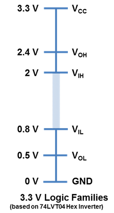
If you take heed to the working range of flash memory, maybe you can think to work at limit of 3.3V Logic Levels to read/write on the SPI Bus. You can find some info to this Adafruit page.
It isn't simple, because to don't make damages you have to calculate the exact currents to power the flash memory that don't damage the SPI Bus.
We got this result!
We just had made the circuit showed below, it was made to work with level shifter (do you remember?). On the right side you can see the headers and on the left side the connector for the clip we made on our breadboard plate.


We have connected a 50 ohm (1% err) resistor to the orange wire pin and this pin to a 1.8V power supply with in series a current meter and then this test configuration on Teclast mainboard. In these conditions we have mesured a current of 13.2mA! This situation is described in the schematic below.

The orange wire makes in connection the pins Power Hold and Wp, then we can think to their to something like a parallel connection.
At the end of calculation of "RX" resistor, we can suppose that every resistor got a resistance for every pin of 300 ohm and that they drain a current of about 6.9mA. It would be true if on the bus it was only the flash memory and we don't know what happen in dynamic conditions (when the bus is active!) because the mainboard is a black box in our consideration.
So, beginning from this configuration, we tested with a DSO the signal on the mainbord and at the end we have found the right configuration of resistors to achieve a stable comunication!
The right configuration is reported in the schematic below.


This configuration allows you to communicate with flash memory, but not with the rest of SPI Bus (on edge level voltage conditions, as we wrote before).
So, if we add this one to the other two following schematics, we obtain our prototype.


As you can see, you can use a traditional level shifter, if you switch to external power supply.

Or in our particular configuration developed for Teclast X98 tablet, if you switch to internal power supply using the 3.3V of Bus Pirate 4.

This makes our hardware extremely scalable.

We are at the end of hardware description.
The last advice we can give you is to clean very carefully the circuit after soldering, this because if you leave some dirty (for example soldering paste) between the communication pins, this could be a problem for flashing, or for communication current, or for parasitic capacities. It's a common forgetfulness to underestimate these small particulars, but in the logic communications Bus it's very important to take in mind these situations.


If you respect all our advices and descriptions, what remains is to connect the programmer to Teclast mainbord. First (if you can) keep under control all output signals. Connect flash clip to Teclast tablet with carefull and then the other side of clip cable to the programmer.
In this conditions you are able to flash your specific BIOS on Teclast tablet, just remains to talk about the software...
We have developed a patch for the BP's driver of flashrom; utility for identifying, reading, writing, verifying and erasing flash chips. This utility supports very well our flash memory, but the base command doesn't allows you to control your BP in every conditions.
No fear, we made this patch and right now you can use every additional commands to:
- Use internal pull-up resistors (pullpus=on/off)
- Use internal power supply (power-in=on/off)
- Use open collector feature (open-drain=on/off)
Be careful. These additional commands work, but are untested for all pins, because our Bus Pirate probably has a problem with the chip 74HC4066D. We have tested it full works in external pullup configuration (with 1.8V external power supply) on CS CLK MISO, but MOSI remains at 3.3V. As wrote, it could be an hardware problem or a firmware support bug on BP4. On Dangerous Prototypes forum we haven't gotten an answer about yet.
What you have to do is to write this command inline with the terminal command.
Now the bad news, flashrom have to be compiled. You can find every info on flashrom web site.
In theory, there is no problem to compile this program under Windows or Linux, but we are much more comfortable to compile the binary under Ubuntu.
What you have to do:
- install all dependencies
- open a terminal window
- write the following commands for compiling
$ svn co svn://flashrom.org/flashrom/trunk flashrom
Now, you have to download our patch from our github page, drag and drop it into flashrom directory to overwrite the original file before continue to write into terminal:
$ cd flashrom
$ make
# The next step is optional!
$ sudo make install
If your Bus Pirate 4 is connected both to your PC and Teclast mainborad, you have to know your serial port, for example ttyACM0, the directory in which is saved the BIOS you want to flashing and then you have to type only:
$ flashrom -p buspirate_spi:dev=/dev/ttyACM0
,spispeed=1M,power-in=on,pullups=off,open-drain=off
-w /xxx/xxBIOSxx.bin
(in a single command)
If things went along as well as we expected, you would have unbrick your tablet; in 15/20 minutes (depending on BIOS).
If you want a verbose screen, you have to add the option -v before -p.
That's all, good luck with your unbrick!
GitHub files.
P.S.
We tested the flashing with internal tablet battery connected.

We think there are no problems to desordering the positive wire of battery for all flashing time.
It's a good thing, but we were in hurry so we took the decision to upgrade the flash with the positive pole of battery connected.
To be absolutely honest, we disconnected the battery for all the time in which we're waiting for the components.
You can do as you wish...
Ottimo! Potreste offrire un servizio di riparazione volendo!
ReplyDeleteSe in provincia di Lecce si, almeno per ora. Abbiamo in programma un trasferimento.
ReplyDeleteGrande!Questo è molto positivo, l'unbrick non è cosa da tutti..Grazie per aver condiviso con tutte le community questa la guida completa di considerazioni!
DeleteThis comment has been removed by the author.
DeleteDear Sir , thz for your share...other way can u free to post level voltage of BusPirate v3.8..??? regards
ReplyDeleteExcuse me for delay, I have tested out the voltage level on BP4 with the kit connected, but without flash on the other side. I found these levels on CLK and CS side.
Deletehttp://s9.postimg.org/qpshi6v6n/IMAG001.png
http://s9.postimg.org/adifsggv3/IMAG002.png
3.3V for every pin.
Ciao Cosimo, mi chiamo Antonio,
ReplyDeletepossiedo un Teclast x98 Air 3g (c5j6) e dopo una settimana circa di utilizzo a seguito, a mio dire, di una banale operazione, il tablet si è spento e non riesco in nessun modo ad accenderlo. Cercavo di avviare, tramite hub usb alimentato, una chiavetta con Aomei Backupper, perchè era mia intenzione poter fare un'immagine dell'intero contenuto della emmc (Android 4.4.4+Win10). Durante il caricamento della chiavetta, dopo cira 3 minuti, una schermata azzurrina mi avvisava di un errore e, con difficoltà, ho potuto leggere dell'intero messaggio solo la parola, ACPI. Dopo si è spento e non ne vuole più sapere di avviarsi. Prima di questa operazione, funzionana egregiamente. Possibile che una banale chiavetta abbia potuto mandare in tilt il bios (winbond 26q64)? Cosa devo fare?
Ciao Antonio, non conosco Aomei Backupper, ma dovresti riportarmi la versione del firmawre e vorrei sapere inoltre se per caso hai fatto il boot da hub alimentato. Riesci ad accedere al bios con una tastiera collegata premendo ESC? Fammi sapere e scusa per il ritardo.
DeleteAfter a flash I have brick my tablet. Now I have the clip and the programmer ordered me to flash the BIOS directly. I have made a mistake. I damaged 2 resistors or other components while placing the clip. Does anyone know the components(I suspect resistors) and what size / unit have those things
ReplyDeleteHello. I installed windows bios on my taclast x 98 tablet and disabled the keyboard. I need to reset the windows bios ( hardware reset). Any hints? (dragusalexandru@yahoo.com)
ReplyDeleteSalve ,pensando d'avere problemi di batteria ho riformattato il tablet inserendo il firmware Android di Mirek190 V7.0 e sia il tablet che la batteria funzionavano alla perfezione fin a quando non ho provato ad installare anche windows in dual boot,ho paura che il mio errore sia stato non utilizzare un Hub alimentato infatti mentre il sistema veniva caricato prima del''interfaccia dell' installazione appare la schermata bul di errore e il tablet dopo pochi secondi si spegne e non si riaccende piu' in nessun modo.E' possibile ripararlo? Fate questo servizio? Grazie per l'attenzione.
ReplyDeleteQualcuno sa come mai la Micro USB non riconosce più i pennini otg ma funziona in ricarica e sincronizza
ReplyDeleteIs this circuit safe to use with the RPi's SPI?
ReplyDelete