

And finally it (...after months of delay) come off in all its beauty.
First of all, we apologize for the lateness of this article with our readers. It's due to a new hectic work activity. We have less and less time to write over this blog, so we thank you once more to keep following us.
We don't want to overstate; we know it's no more than a cube ....or something like this, but after lots of checks hardware and software (and after trying it for a while) we can assume that it work as expected.
In this release, we have fixed the preview schematic as shown below and we added some sensors for interesting features. We suggest you to take a look to new schematic first of all, if you want to make a correct circuit. Then you can make all about the case with all details we are going to describe.

So, we start with case description. To make it, we use two pieces of aluminium heatsinks to dissipate the heat of leds and mosfet. The program inside Slenduino it's already optimized to achieve the best energy saving from the batteries, but if you end up in a software error by chance, these heatsinks can save you from a disaster (absolutely suggested!).
We forgotten... The Batteries.
If you remember, in the preview solution we have chosen how battery for the project a 12V acid lead battery. If you prefer this solution isn't a problem, you can reprogram the Slenduino to support a 12V battery. But, if you want to carry the project away, we suggest you our solution, that's two 18650 lipo batteries of 3.6V!


Right now, you can ask us where we have found these kind of batteries. If you are in US or UK, we think there's no problem to find them in some shop close to your home, but if you lives in Italy these batteries are expensive (wherever you going to look for).
So, we suggest you a simple, practical and ecological solution. If you have had a notebook, you already known that sooner or later you'll be forced to change the battery, but don't throw things away so easily!
Usually, it contain more less six batteries you can use for your project. Not every battery should be good for a regeneration and a new life, but if you have just bit of luck you can recover (with an external charger) at least five batteries.
So, now you have your batteries.
How you can connect them to the project? Simple, in series.
But, is it difficult to find a charger for them? More or less.. yes in series, not in parallel.
So, you'd like to have the batteries in parallel to charge them more easily, but you'd like to have them in series to power the project.
Is it possible? Yes, with a simple trick. Make your batterie holder by yourself!
How?! Like this...

The idea is very simple, when you want to charge the batteries, you'll get them in parallel mode with a short circuit between the two ends of external header fixed to positive pin of charger. Then, continue to add another short circuit between the two ends of internal ones fixed to the negative pin of charger.
When you want to power the project you can change in series mode the battery holder. Simply connect one positive pin of a battery with another negative one corresponding to a different battery of battery holder. Then the others positive and negative will be the series battery pins. That's easier done than said of course!
Now, we show you how to make the case below.


This unique piece is for left, right and down side of our case. You can bend it over two pieces of aluminium heatsinks connected together to make the base of case structure. There's even the grooves for the PCB, to put it in inside without problem. The two pieces on the upperside can be achieved to fix in place the power leds.

This piece in picture completes the back and front side of case, on the right piece you can see the slot achieved to fix in place the glass that cover in front the two leds. The result below.


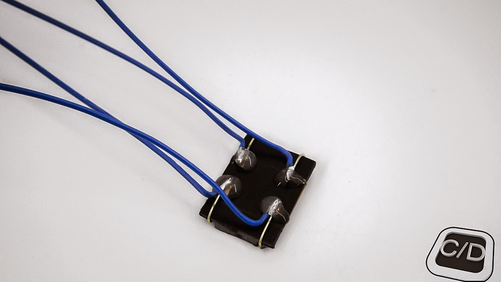
We have added a piece with velcro to fix in place the battery older and left the screws, such as in picture, to block any movement of battery holder. You can even see the pins of internal circuit where the battery holder will be connected.

Right here, you can see in the picture with the sensor extension that we made to power up the circuit in flash mode.


Right here the back and front side of battery holder pins.


Now, we're going to describe the last sensor we made to select the flash mode and the normal mode of lamp. It's consists of two reed switches and a magnetic slider outside the case.


When the magnetic slider produce a magnetic field over the first reed, it select the normal mode, as well as if you continue to move the slider, you select the flash mode and the sensor will be enabled. In this state, the flash can read and external flash signal to execute the "flash code" into Slenduino source. It follows your phone camera flash and highlights your photographic performance of your camera software.


Remains just a piece to be dealt in the description, it's the phone connector.


It's consists of some pieces that you can slide in and out of the lamp (close to the screws), to fix it in place on your phone. It's useful to connect the lamp in a particular place of phone over the flash led.
Whereas every phone is different, this case piece is essential to give you the best positioning. So, to help you with disposition, we arrange some velcro on it to simplify the connection, fixing and removing.


After you have applied phone connector to the back side of case, you can put over the battery holder, as shown below.


That's all for the hardware side, now remains only to discuss the code we made for Slenduino board.
The main code is just as we described in the hardware section such as steps.
"
start:"
Set PWMpin On
If Button1 Then
'Increase Power of Slamp
'840 = 82% of 1024
If ReadAD10(Sensor) >= 840 Then
time = 6000
For i = 0 To time
'2/3 of second Flash
_052_56
Next
End If
Else
'Switch On
For i = 0 To 9000
_090_18
Next
End If
Goto start
You can choose different settings for flash and normal mode, in runtime, to generate a voltage between 18.2V to 24.2V. All about that it was tested (with an oscilloscope) and reported into the complete code, such as the example below.
"
Sub _052_56"
'24,2V output
Set PWMpin On
Wait 52 us
Set PWMpin Off
Wait 56 us
End Sub
There are as much settings as possible subroutines you can choose. We leave you to the final GCGB code for any information.

Thank you to have followed us since here, stay tuned for upcoming projects.
New schematic, board and code on github.
No comments:
Post a Comment
Hi at all, leave me a feedback for this post. Thx